Czytaj, na gotowca? ![]() …myślę że i tak później będziesz męczył bułę.
…myślę że i tak później będziesz męczył bułę.
Wszystkie szczegóły już masz. Nie czekaj więc, tylko bezpośrednio możesz czytać z falownika integracją modbus. Zdobędziesz jakieś doświadczenie.
Dziękuje za wskazanie kierunku. Udało się połączyć z falownikiem. W kodzie trzeba zamienić tx z rx.
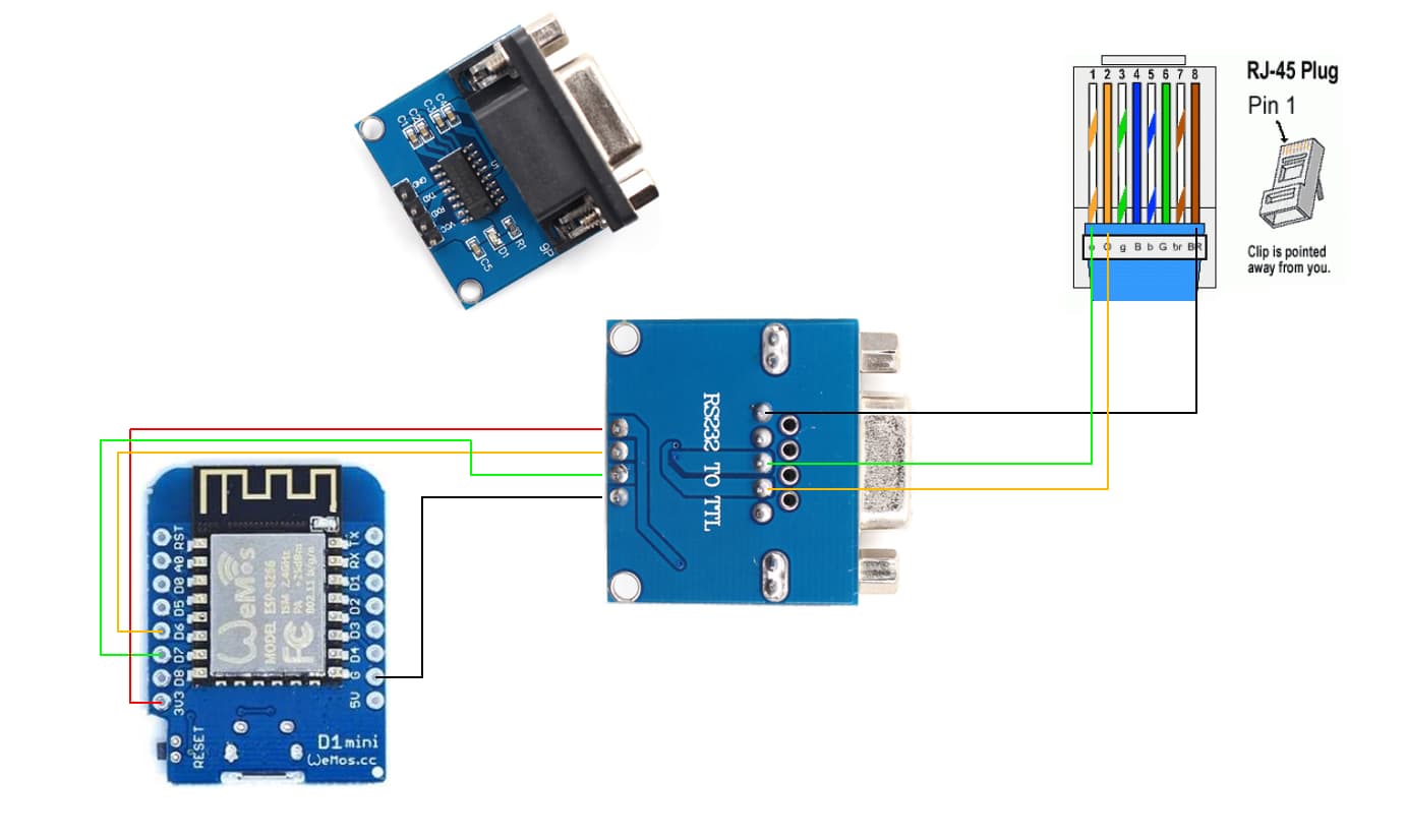
Podłączenie:
Jeśli w YAMLu musisz zamienić TX z RX to znaczy, że coś jest zwalone w tym YAMLu w innym miejscu (bo użycie pinó RX i TX niezgodnie z przeznaczeniem wyłącza sprzętowy UART i na ych samych pinach dostajesz UART programowy, jak przypuszczam sądząc po obrazku z D1 mini zapewne nie wyłączyłeś loggera w sprzęcie który ma tylko jeden UART)
UART0 nie jest na “wędrujących pinach” w ESP8266, więc albo definiujesz je zgodnie ze sprzętem i masz UART sprzętowy albo niezgodnie i wtedy zostaje on odłączony a piny są przełączane na wewnętrznej krosownicy do pracy jako zwykłe GPIO, na które można wysłać tylko emulację UART.
Jeśli coś projektujesz w oparciu o jakiś mikrokontroler, to praktycznie zawsze musisz się liczyć z jakimiś ograniczeniami sprzętu, w tym faktem, że zawsze jakieś piny będą “święte”, bo np. stanowią port potrzebny do flashowania lub debugowania, czy w ogóle wprowadzenia sprzętu w tryb bootloadera albo wręcz konfigurowania kluczowych parametrów pracy (np. poziomu napięć magistrali łączącej z RAMem czy flashem - takie rzeczy to w ESP32), zwykle kluczowe magistrale są przypisane na stałe do pewnych pinów (i nie zawsze mogą być one alternatywnie traktowane jako GPIO).
Zrób proszę w tym poście poradnik od A-z jak to zrobić jestem na etapie właśnie robienia czegoś takiego tylko trochę się pogubiłem jaki kod wkleić itp co jak ustawić. A bez sensu jest żebym zaśmiecał forum, jakbyś mógł wkleić kodowe koy i zrobić poradnik było by super
Jakiego użyłeś kodu ? podeślesz coś?
Podpowiesz co zrobiłeś żeby zadziałało? Bo właśnie wpiąłem się w RS232 mojego Anenji przez pipsolar a tam cisza.
EDIT:
pipsolar nie działa po modbus. Tutaj repo do smg-ii ale działa również z Anenji 6.2:
https://github.com/syssi/esphome-smg-ii
Nie wiem do czego się to odnosi, bo jakoś intensywnie nie śledzę tego wątku
cytat z podlinkowanego repo
The protocol is Modbus RTU via RS232.
Autor wątku zaczął od pipsolar ponieważ większość chińskich inwerterów tamten projekt ogarnia.
Natomiast w niektórych przypadkach inwertery komunikują się po modbus więc pipsolar odpada i trzeba użyć użyć kodu z repo esphome-smg-ii
1 polubienie
Witam serdecznie. Ja mam pytanie retoryczne odnośnie schematu. Nie lepiej byłoby wziąć napięcie ze złącza RJ45 12V i przez jakąś przetwornicę zmienić je na +5. Dodatkowo przy RS232 dołożyć kondensatory 22u i 100n do dobrej filtracji napięcia. W ten sposób usamodzielnionymi te urządzenie, gdy zostanie podłączone go złącza RJ45 do inwertera. Prace nad softwarowe będę sprawdzał po powrocie do domu z przymusowego wyjazdu.
Ja mam komunikacjęz bms na RJ45
@Dyzio podrzuciłbyś swojego yamla ? Co tam konkretnie trzeba zamienić żeby to zadziałało bo mecze się z tym już kilka dni i nie mogę połączyć się z falownikiem. Byłbym wdzieczny.
Witam Serdecznie,
Sorry za długi czas oczekiwania na post z kompletnym rozwiązaniem (działającym u mnie)
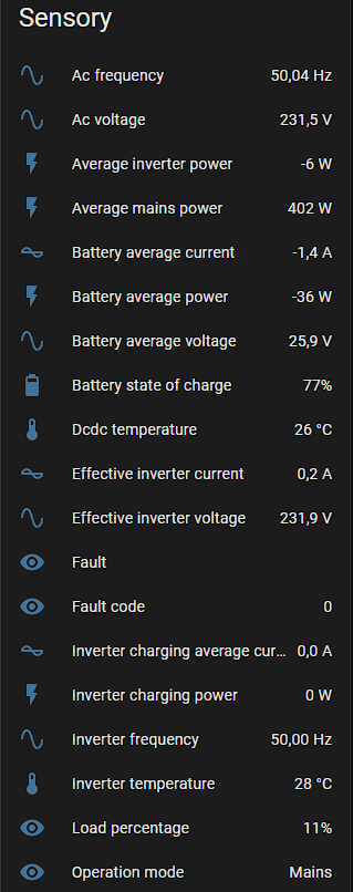
Poniżej wrzucę, mam nadzieje zebrane wszystko w jednym miejscu. Integracja działa u mnie już dłuższy czas, stabilnie oraz czasy odczytu/przesyłania danych jest akceptowalnie szybki.
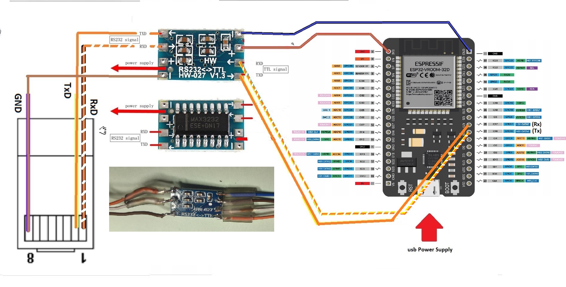
Falownik Anenji 4kw - ESP32 wroom + konwerter RS232 - TTL
ANJ-4000W-24V-WIFI.zip (4,4 MB)
(to absolutnie nie reklama, wklejam linki do dokładnie tych elementów, które ja użyłem)
Połączenia ESP32 ----> TTL / RS232 zakończony wtykiem rj45
Kod do ESP Home:
esphome:
name: esp32-pv
friendly_name: ESP32_PV
esp32:
board: upesy_wroom
logger:
baud_rate: 0
api:
encryption:
key: "2TzuvKsblhk7YxxxxxxxxxxVPBrvMs4oIS2vC+y5gi0="
ota:
- platform: esphome
password: "cefb124dd533xxxxxxxxxxf4fe08039"
wifi:
ssid: !secret wifi_ssid
password: !secret wifi_password
ap:
ssid: "Esp32-Pv Fallback Hotspot"
password: "4RauxxxxxuvoJn"
substitutions:
name: ANENJI
device_description: "Monitor and control a ISolar/EASUN SMG II inverter via RS232"
tx_pin: GPIO16
rx_pin: GPIO17
captive_portal:
uart:
- id: uart_0
baud_rate: 9600
tx_pin: ${tx_pin}
rx_pin: ${rx_pin}
modbus:
- id: modbus0
uart_id: uart_0
send_wait_time: 200ms
modbus_controller:
- id: smg0
address: 0x01
modbus_id: modbus0
command_throttle: 200ms
update_interval: 10s
time:
- platform: sntp
sensor:
- platform: total_daily_energy
name: "Dzienna Produkcja"
restore: true
icon: mdi:counter
power_id: smg0_pv_average_power
filters:
# Multiplication factor from W to kW is 0.001
- multiply: 0.001
unit_of_measurement: kWh
# Fault code ULong 100 2 R
- platform: modbus_controller
modbus_controller_id: smg0
name: "Kod Błędu"
address: 100
register_type: holding
value_type: U_DWORD
accuracy_decimals: 0
# Warning code ULong 108 2 R
- platform: modbus_controller
modbus_controller_id: smg0
name: "${name} warning code"
address: 108
register_type: holding
value_type: U_DWORD
accuracy_decimals: 0
# Operation Mode UInt 201 1 R 0: Power On
# 1: Standby
# 2: Mains
# 3: Off-Grid
# 4: Bypass
# 5: Charging
# 6: Fault
- platform: modbus_controller
modbus_controller_id: smg0
name: "${name} operation mode id"
address: 201
register_type: holding
value_type: U_WORD
accuracy_decimals: 0
# Effective mains voltage 0.1V Int 202 1 R
- platform: modbus_controller
modbus_controller_id: smg0
name: "Napięcie AC"
address: 202
register_type: holding
value_type: S_WORD
unit_of_measurement: "V"
device_class: voltage
state_class: measurement
accuracy_decimals: 1
filters:
- multiply: 0.1
# Mains Frequency 0.01Hz Int 203 1 R
- platform: modbus_controller
modbus_controller_id: smg0
name: "${name} ac frequency"
address: 203
register_type: holding
value_type: S_WORD
unit_of_measurement: "Hz"
device_class: frequency
state_class: measurement
accuracy_decimals: 2
filters:
- multiply: 0.01
# Average mains power 1W Int 204 1 R
- platform: modbus_controller
modbus_controller_id: smg0
name: "MOC Z SIECI"
address: 204
register_type: holding
value_type: S_WORD
unit_of_measurement: "W"
device_class: power
state_class: measurement
accuracy_decimals: 0
# Effective inverter voltage 0.1V Int 205 1 R
- platform: modbus_controller
modbus_controller_id: smg0
name: "${name} Prąd AC"
address: 205
register_type: holding
value_type: S_WORD
unit_of_measurement: "V"
device_class: voltage
state_class: measurement
accuracy_decimals: 1
filters:
- multiply: 0.1
# Effective inverter current 0.1A Int 206 1 R
- platform: modbus_controller
modbus_controller_id: smg0
name: "${name} NAPIĘCIE AC"
address: 206
register_type: holding
value_type: S_WORD
unit_of_measurement: "A"
device_class: current
state_class: measurement
accuracy_decimals: 1
filters:
- multiply: 0.1
# Inverter frequency 0.01Hz Int 207 1 R
- platform: modbus_controller
modbus_controller_id: smg0
name: "${name} inverter frequency"
address: 207
register_type: holding
value_type: S_WORD
unit_of_measurement: "Hz"
device_class: frequency
state_class: measurement
accuracy_decimals: 2
filters:
- multiply: 0.01
# Average inverter power 1W Int 208 1 R Positive numbers indicate inverter output, negative numbers indicate inverter input
- platform: modbus_controller
modbus_controller_id: smg0
name: "${name} MOC"
address: 208
register_type: holding
value_type: S_WORD
unit_of_measurement: "W"
device_class: power
state_class: measurement
accuracy_decimals: 0
# Inverter charging power 1W Int 209 1 R
- platform: modbus_controller
modbus_controller_id: smg0
name: "${name} MOC Ładowania"
address: 209
register_type: holding
value_type: S_WORD
unit_of_measurement: "W"
device_class: power
state_class: measurement
accuracy_decimals: 0
# Output effective voltage 0.1V Int 210 1 R
- platform: modbus_controller
modbus_controller_id: smg0
name: "PRĄD WYJŚCIA"
address: 210
register_type: holding
value_type: S_WORD
unit_of_measurement: "V"
device_class: voltage
state_class: measurement
accuracy_decimals: 1
filters:
- multiply: 0.1
# Output effective Current 0.1A Int 211 1 R
- platform: modbus_controller
modbus_controller_id: smg0
name: "MOC WYJŚCIA"
address: 211
register_type: holding
value_type: S_WORD
unit_of_measurement: "A"
device_class: current
state_class: measurement
accuracy_decimals: 1
filters:
- multiply: 0.1
# Output frequency 0.01Hz Int 212 1 R
- platform: modbus_controller
modbus_controller_id: smg0
name: "${name} output frequency"
address: 212
register_type: holding
value_type: S_WORD
unit_of_measurement: "Hz"
device_class: frequency
state_class: measurement
accuracy_decimals: 2
filters:
- multiply: 0.01
# Output active power 1W Int 213 1 R
- platform: modbus_controller
modbus_controller_id: smg0
name: "MOC OBCIĄŻENIE INWERTERA"
address: 213
register_type: holding
value_type: S_WORD
unit_of_measurement: "W"
device_class: power
state_class: measurement
accuracy_decimals: 0
# Output apparent power 1VA Int 214 1 R
- platform: modbus_controller
modbus_controller_id: smg0
name: "${name} output apparent power"
address: 214
register_type: holding
value_type: S_WORD
unit_of_measurement: "VA"
device_class: apparent_power
state_class: measurement
accuracy_decimals: 0
# Battery average voltage 0.1V Int 215 1 R
- platform: modbus_controller
modbus_controller_id: smg0
name: "NAPIĘCIE Z BATERII"
address: 215
register_type: holding
value_type: S_WORD
unit_of_measurement: "V"
device_class: voltage
state_class: measurement
accuracy_decimals: 1
filters:
- multiply: 0.1
# Battery average Current 0.1A Int 216 1 R
- platform: modbus_controller
modbus_controller_id: smg0
name: "PRĄD Z BATERII"
address: 216
register_type: holding
value_type: S_WORD
unit_of_measurement: "A"
device_class: current
state_class: measurement
accuracy_decimals: 1
filters:
- multiply: 0.1
# Battery average power 1W Int 217 1 R
- platform: modbus_controller
modbus_controller_id: smg0
name: "MOC Z BATERII"
address: 217
register_type: holding
value_type: S_WORD
unit_of_measurement: "W"
device_class: power
state_class: measurement
accuracy_decimals: 0
# PV average voltage 0.1V Int 219 1 R
- platform: modbus_controller
modbus_controller_id: smg0
name: "Napięcie PV"
address: 219
register_type: holding
value_type: S_WORD
unit_of_measurement: "V"
device_class: voltage
state_class: measurement
accuracy_decimals: 1
filters:
- multiply: 0.1
# PV average current 0.1A Int 220 1 R
- platform: modbus_controller
modbus_controller_id: smg0
name: "PRĄD Z PRODUKCJI PV"
address: 220
register_type: holding
value_type: S_WORD
unit_of_measurement: "A"
device_class: current
state_class: measurement
accuracy_decimals: 1
filters:
- multiply: 0.1
# PV average power 1W Int 223 1 R
- platform: modbus_controller
modbus_controller_id: smg0
id: smg0_pv_average_power
name: "MOC Z PANEL"
address: 223
register_type: holding
value_type: S_WORD
unit_of_measurement: "W"
device_class: power
state_class: measurement
accuracy_decimals: 0
# PV charging average power 1W Int 224 1 R
- platform: modbus_controller
modbus_controller_id: smg0
name: "ŁADOWANIE AKU Z PV"
address: 224
register_type: holding
value_type: S_WORD
unit_of_measurement: "W"
device_class: power
state_class: measurement
accuracy_decimals: 0
# Load percentage 1% Int 225 1 R
- platform: modbus_controller
modbus_controller_id: smg0
name: "OBCIĄŻENIA INVERTERA"
address: 225
register_type: holding
value_type: S_WORD
unit_of_measurement: "%"
# device_class: battery
state_class: measurement
accuracy_decimals: 0
# DCDC Temperature 1°C Int 226 1 R
- platform: modbus_controller
modbus_controller_id: smg0
name: "TEMPERATURA PRZETWORNICY"
address: 226
register_type: holding
value_type: S_WORD
unit_of_measurement: "°C"
device_class: temperature
state_class: measurement
accuracy_decimals: 0
# Inverter Temperature 1°C Int 227 1 R
- platform: modbus_controller
modbus_controller_id: smg0
name: "TEMPERATURA INWERTERA"
address: 227
register_type: holding
value_type: S_WORD
unit_of_measurement: "°C"
device_class: temperature
state_class: measurement
accuracy_decimals: 0
# Battery state of charge 1% UInt 229 1 R
- platform: modbus_controller
modbus_controller_id: smg0
name: "POZIOM BANKU ENERGII"
address: 229
register_type: holding
value_type: U_WORD
unit_of_measurement: "%"
device_class: battery
state_class: measurement
accuracy_decimals: 0
# Battery average current 0.1A Int 232 1 R Positive number means charging, negative number means discharging
- platform: modbus_controller
modbus_controller_id: smg0
name: "PRĄD AKUMULATORA"
address: 232
register_type: holding
value_type: S_WORD
unit_of_measurement: "A"
device_class: current
state_class: measurement
accuracy_decimals: 1
filters:
- multiply: 0.1
# Inverter charging average current 0.1A Int 233 1 R
- platform: modbus_controller
modbus_controller_id: smg0
name: "PRĄD ŁADOWANIA INWERTERA"
address: 233
register_type: holding
value_type: S_WORD
unit_of_measurement: "A"
device_class: current
state_class: measurement
accuracy_decimals: 1
filters:
- multiply: 0.1
# PV charging average current 0.1A Int 234 1 R
- platform: modbus_controller
modbus_controller_id: smg0
name: "PRĄD ŁADOWANIA Z PV"
address: 234
register_type: holding
value_type: S_WORD
unit_of_measurement: "A"
device_class: current
state_class: measurement
accuracy_decimals: 1
filters:
- multiply: 0.1
# # Output voltage 0.1V Uint 320 1 R/W
# - platform: modbus_controller
# modbus_controller_id: smg0
# name: "${name} output voltage"
# address: 320
# register_type: holding
# value_type: U_WORD
# unit_of_measurement: "V"
# device_class: voltage
# # state_class: measurement
# accuracy_decimals: 1
# filters:
# - multiply: 0.1
# # Output frequency setting 0.01Hz Uint 321 1 R/W
# - platform: modbus_controller
# modbus_controller_id: smg0
# name: "${name} output frequency setting"
# address: 321
# register_type: holding
# value_type: U_WORD
# unit_of_measurement: "Hz"
# device_class: frequency
# # state_class: measurement
# accuracy_decimals: 2
# filters:
# - multiply: 0.01
# # Battery overvoltage protection point 0.1V Uint 323 1 R/W
# - platform: modbus_controller
# modbus_controller_id: smg0
# name: "${name} battery overvoltage protection point"
# address: 323
# register_type: holding
# value_type: U_WORD
# unit_of_measurement: "V"
# device_class: voltage
# # state_class: measurement
# accuracy_decimals: 1
# filters:
# - multiply: 0.1
# # Max charging voltage 0.1V Uint 324 1 R/W
# - platform: modbus_controller
# modbus_controller_id: smg0
# name: "${name} max charging voltage"
# address: 324
# register_type: holding
# value_type: U_WORD
# unit_of_measurement: "V"
# device_class: voltage
# # state_class: measurement
# accuracy_decimals: 1
# filters:
# - multiply: 0.1
# # Floating charging voltage 0.1V Uint 325 1 R/W
# - platform: modbus_controller
# modbus_controller_id: smg0
# name: "${name} floating charging voltage"
# address: 325
# register_type: holding
# value_type: U_WORD
# unit_of_measurement: "V"
# device_class: voltage
# # state_class: measurement
# accuracy_decimals: 1
# filters:
# - multiply: 0.1
# # Battery discharge recovery point in mains mode 0.1V Uint 326 1 R/W
# - platform: modbus_controller
# modbus_controller_id: smg0
# name: "${name} battery discharge recovery point in mains mode"
# address: 326
# register_type: holding
# value_type: U_WORD
# unit_of_measurement: "V"
# device_class: voltage
# # state_class: measurement
# accuracy_decimals: 1
# filters:
# - multiply: 0.1
# # Battery low voltage protection point in mains mode 0.1V Uint 327 1 R/W
# - platform: modbus_controller
# modbus_controller_id: smg0
# name: "${name} battery low voltage protection point in mains mode"
# address: 327
# register_type: holding
# value_type: U_WORD
# unit_of_measurement: "V"
# device_class: voltage
# # state_class: measurement
# accuracy_decimals: 1
# filters:
# - multiply: 0.1
# # Battery low voltage protection point in off-grid mode 0.1V Uint 329 1 R/W
# - platform: modbus_controller
# modbus_controller_id: smg0
# name: "${name} battery low voltage protection point in off-grid mode"
# address: 329
# register_type: holding
# value_type: U_WORD
# unit_of_measurement: "V"
# device_class: voltage
# # state_class: measurement
# accuracy_decimals: 1
# filters:
# - multiply: 0.1
# # Maximum charging current 0.1A Uint 332 1 R/W
# - platform: modbus_controller
# modbus_controller_id: smg0
# name: "${name} maximum charging current"
# address: 332
# register_type: holding
# value_type: U_WORD
# unit_of_measurement: "A"
# device_class: current
# # state_class: measurement
# accuracy_decimals: 1
# filters:
# - multiply: 0.1
# # Maximum mains charging current 0.1A Uint 333 1 R/W
# - platform: modbus_controller
# modbus_controller_id: smg0
# name: "${name} maximum mains charging current"
# address: 333
# register_type: holding
# value_type: U_WORD
# unit_of_measurement: "A"
# device_class: current
# # state_class: measurement
# accuracy_decimals: 1
# filters:
# - multiply: 0.1
# # Eq Charging voltage 0.1V Uint 334 1 R/W
# - platform: modbus_controller
# modbus_controller_id: smg0
# name: "${name} Eq Charging voltage"
# address: 334
# register_type: holding
# value_type: U_WORD
# unit_of_measurement: "V"
# device_class: voltage
# # state_class: measurement
# accuracy_decimals: 1
# filters:
# - multiply: 0.1
# Rated power W Uint 643 1 R
- platform: modbus_controller
modbus_controller_id: smg0
name: "${name} rated power"
address: 643
register_type: holding
value_type: U_WORD
unit_of_measurement: "W"
device_class: power
# state_class: measurement
accuracy_decimals: 0
select:
# Output Mode Uint 300 1 R/W 0: Single, 1: Parallel, 2: 3 Phase-P1, 3: 3 Phase-P2, 4: 3 Phase-P3
- platform: modbus_controller
modbus_controller_id: smg0
name: "${name} output mode"
use_write_multiple: true
address: 300
value_type: U_WORD
optionsmap:
"Single": 0
"Parallel": 1
"Phase P1": 2
"Phase P2": 3
"Phase P3": 4
# Output priority Uint 301 1 R/W 0: Utility-PV-Battery, 1: PV-Utility-Battery, 2: PV-Battery-Utility
- platform: modbus_controller
modbus_controller_id: smg0
name: "${name} output priority"
use_write_multiple: true
address: 301
value_type: U_WORD
optionsmap:
"Utility-PV-Battery (UTI)": 0
"PV-Utility-Battery (SOL)": 1
"PV-Battery-Utility (SBU)": 2
V-Utility-Battery (SUB)": 3
# Input voltage range Uint 302 1 R/W 0: Wide range, 1: Narrow range
- platform: modbus_controller
modbus_controller_id: smg0
name: "${name} input voltage range"
use_write_multiple: true
address: 302
value_type: U_WORD
optionsmap:
"Wide range": 0
"Narrow range":
switch:
# LCD automatically returns to the homepage Uint 306 1 R/W 0: Do not return automatically, 1: Automatically return after 1 minute
- platform: modbus_controller
modbus_controller_id: smg0
name: "${name} lcd automatically returns to the homepage"
use_write_multiple: true
address: 306
register_type: holding
bitmask: 1
# Energy-saving mode Uint 307 1 R/W 0: Energy-saving mode is off, 1: Energy-saving mode is on
- platform: modbus_controller
modbus_controller_id: smg0
name: "${name} energy-saving mode"
use_write_multiple: true
address: 307
register_type: holding
bitmask: 1
# Battery Eq mode is enabled Uint 313 1 R/W 0: Disable, 1: Enable
- platform: modbus_controller
modbus_controller_id: smg0
name: "${name} battery Eq mode is enabled"
use_write_multiple: true
address: 313
register_type: holding
bitmask: 1
# Remote switch Uint 420 1 R/W 0: Remote shutdown, 1: Remote turn-on
- platform: modbus_controller
modbus_controller_id: smg0
name: "${name} remote switch"
use_write_multiple: true
address: 420
register_type: holding
bitmask: 1
text_sensor:
# Operation Mode UInt 201 1 R 0: Power On, 1: Standby, 2: Mains, 3: Off-Grid, 4: Bypass, 5: Charging, 6: Fault
- platform: modbus_controller
modbus_controller_id: smg0
name: "Tryb Pracy"
address: 201
register_type: holding
raw_encode: HEXBYTES
lambda: |-
uint16_t value = modbus_controller::word_from_hex_str(x, 0);
switch (value) {
case 0: return std::string("Power On");
case 1: return std::string("Standby");
case 2: return std::string("Mains");
case 3: return std::string("Off-Grid");
case 4: return std::string("Bypass");
case 5: return std::string("Charging");
case 6: return std::string("Fault");
}
return std::string("Unknown");
number:
# Output voltage 0.1V Uint 320 1 R/W
- platform: modbus_controller
modbus_controller_id: smg0
name: "${name} output voltage"
use_write_multiple: true
address: 320
register_type: holding
value_type: U_WORD
min_value: 0.0
# max_value: 100.0
step: 0.1
unit_of_measurement: "V"
lambda: "return x * 0.1f;"
write_lambda: |-
return x * 10.0f;
# Output frequency setting 0.01Hz Uint 321 1 R/W
- platform: modbus_controller
modbus_controller_id: smg0
name: "${name} output frequency setting"
use_write_multiple: true
address: 321
register_type: holding
value_type: U_WORD
min_value: 0.0
# max_value: 100.0
step: 0.01
unit_of_measurement: "Hz"
lambda: "return x * 0.01f;"
write_lambda: |-
return x * 100.0f;
# Battery overvoltage protection point 0.1V Uint 323 1 R/W
- platform: modbus_controller
modbus_controller_id: smg0
name: "${name} battery overvoltage protection point"
use_write_multiple: true
address: 323
register_type: holding
value_type: U_WORD
min_value: 0.0
# max_value: 100.0
step: 0.1
unit_of_measurement: "V"
lambda: "return x * 0.1f;"
write_lambda: |-
return x * 10.0f;
# Max charging voltage 0.1V Uint 324 1 R/W
- platform: modbus_controller
modbus_controller_id: smg0
name: "${name} max charging voltage"
use_write_multiple: true
address: 324
register_type: holding
value_type: U_WORD
min_value: 0.0
max_value: 100.0
step: 0.1
unit_of_measurement: "V"
lambda: "return x * 0.1f;"
write_lambda: |-
return x * 10.0f;
# Floating charging voltage 0.1V Uint 325 1 R/W
- platform: modbus_controller
modbus_controller_id: smg0
name: "${name} floating charging voltage"
use_write_multiple: true
address: 325
register_type: holding
value_type: U_WORD
min_value: 0.0
# max_value: 100.0
step: 0.1
unit_of_measurement: "V"
lambda: "return x * 0.1f;"
write_lambda: |-
return x * 10.0f;
# Equalization Timeout exit min Uint 336 1 R/W Range: 0~900
- platform: modbus_controller
modbus_controller_id: smg0
name: "${name} equalization Timeout exit"
use_write_multiple: true
address: 336
register_type: holding
value_type: U_WORD
min_value: 0.0
max_value: 900.0
step: 1
unit_of_measurement: "min"
# Two equalization charging intervals day Uint 337 1 R/W Range: 1~90
- platform: modbus_controller
modbus_controller_id: smg0
name: "${name} two equalization charging intervals"
use_write_multiple: true
address: 337
register_type: holding
value_type: U_WORD
min_value: 0.0
max_value: 90.0
step: 1
unit_of_measurement: "day"
# Button entities
# Exit the fault mode Uint 426 W 1: Exit the fault state(only when the inverter enters the fault mode , it could be available)
plik z kompletnym .yaml
Anenji.zip (5,0 KB)
W kodzie zrobiłem zmiany wg. swoich potrzeb, wrzucam całość aby każdy mógł dostosować go do siebie.
3 polubienia
Witam serdecznie.
Buduje wsad do ESP32 ktory wspolpracuje przez modbus i chce zmienic opcje wpisania wartosci czestotliwosci invertera z pisanego:
  - platform: modbus_controller
    modbus_controller_id: anj     #smg0
    name: "${name} Output Frequency Setting 09"
    use_write_multiple: true
    address: 321
    register_type: holding
    value_type: U_WORD
    min_value: 0.0
    # max_value: 100.0
    step: 0.01
    unit_of_measurement: "Hz"
    lambda: "return x * 0.01f;"
    write_lambda: |-
      return x * 100.0f;
na opcje wyboru:
  - platform: modbus_controller
    modbus_controller_id: anj     #smg0
    name: "${name} Output Frequency Setting 09"
    use_write_multiple: true
    address: 321
    value_type: U_WORD
    optionsmap:
      "50 Hz": 5000
      "60 Hz": 6000
Odczyt jest ok, niestety nie zapisuje mi to do invertera, Gdzie robie blad?
Cześć
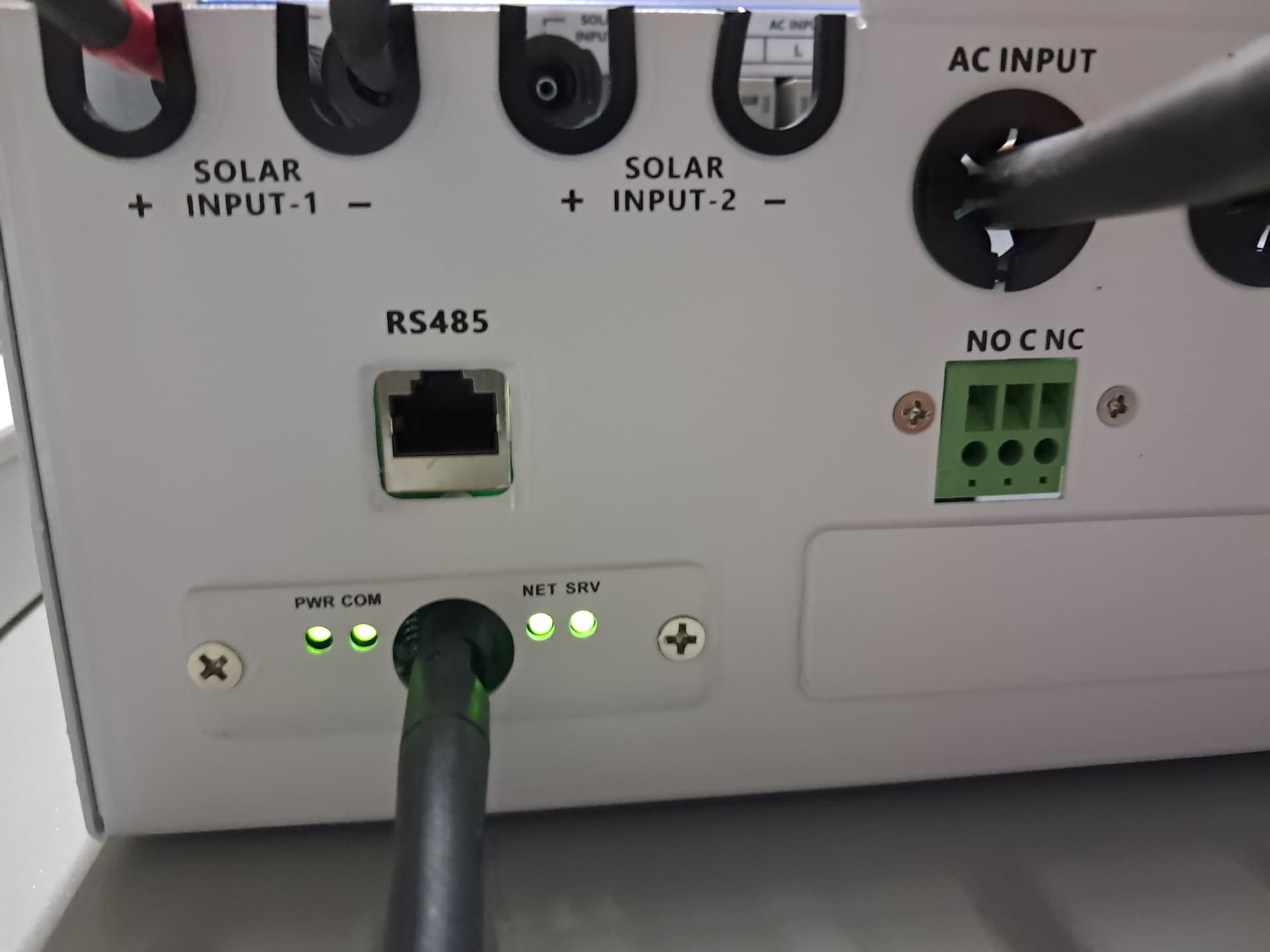
Miałem zabrać się za integracje anenji 11kW z HA, ale okazało się, że falownik który kupiłem to najnowsza wersja która nie posiada RS232 tylko sam RS485 i zintegrowany moduł wifi
Póki co zintegrowałem dziada przez integracje DESS Monitor ale tam niestety posiadam tylko trzy podstawowe pomiary Moc PV, Obciążenie Falownika, Procent naładowania akumulatora. Te parametry odświeżają się co 10 minut trochę słabo. Ktoś podpowie mi dlaczego tylko trzy pierwsze encje mi działają a reszta nie? Część encji wskazuje wartość 0 ale te wartości przez kilka dni się nie zmieniały zawsze jest 0

Jaką różnicę Ci to robi? W warstwie protokołu będzie tak samo (pytanie - odpowiedź).
Czesc , tez mam pecha i falownik z tym zintegrowanym modułem .Odpalilem kontener na docker jako gateway do dessmonitor i tam jest wiecej danych które splywaja do HA ale i tak kod wymaga poprawy bo kod z hub.docker.com/r/antoxa1081/smart-ess-api-gateway ogarnia tylko pierwsze PV. Port rs485 milczy … sprzedawca z alli tez … support z Anenji pomaga tylko tym którzy kupili przez ich strone ![]() …
…
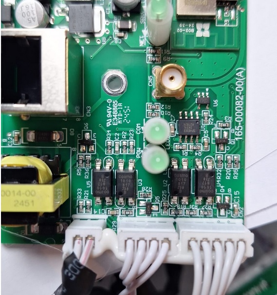
Złaczki od lewej : AC 89V , USB 3.2v ( mam watpliwosci co do oznaczenia na plycie kontrolera MCU w srodku falownika ) ostanie złacze jest dla mnie bez znaczenia bo steruje przekaznikiem . Modułu wifi/BT nie udalo mi sie zidentyfikowac w internecie … chyba pozbawie go tego metalowego kapturka zeby zobaczyc jaki scalak siedzi w srodku i wtedy mozna go wywalic i zastapic esp32 plus esphome z modbus ( to juz mam opanowane ). Jeszcze jedan opcja jest do rozwazenia : po dopieciu sie modulu do SmartESS moduł wystawia w lokalnej sieci serwer www i tu moze uda sie do niego zalogowac i zobaczyc co tam w srodku lata.
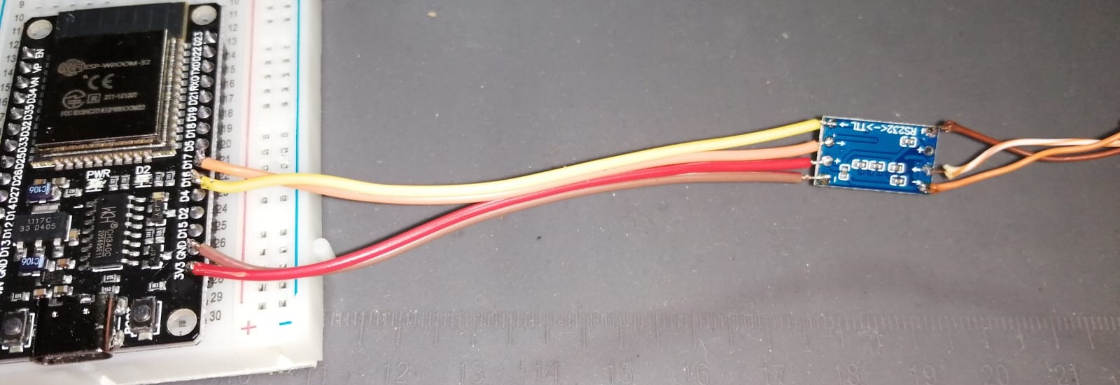
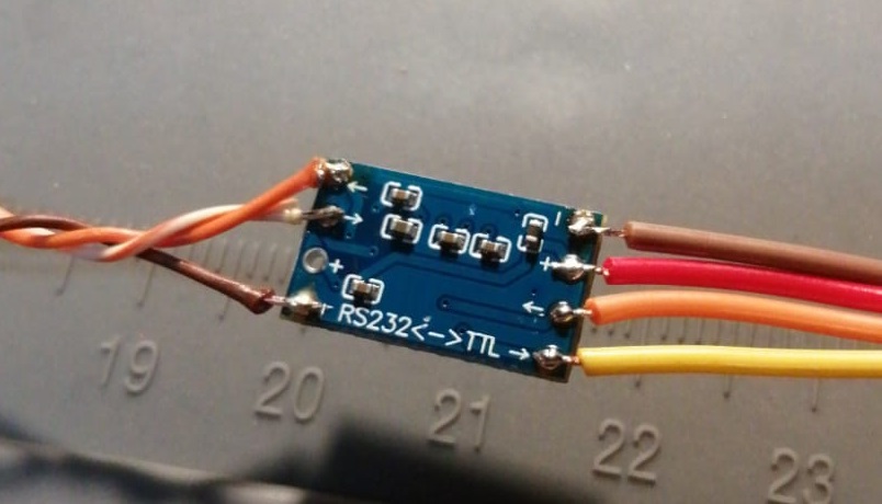
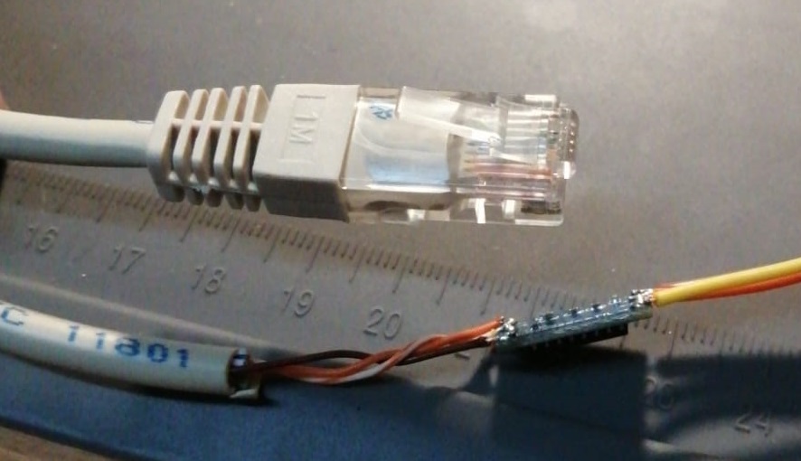
Skorzystałem z wątku, więc dorzucę swoje trzy grosze. Najważniejszy w tym wszystkim jest dobry start - czyli poprawne wykonanie konwertera. W zamieszczonym powyżej filmie wkradł się błąd w połączeniu kablowym pomiędzy wtyczką RS wychodzącą z falownika, a MAX3232. Poniżej rysunek właściwego połączenia:
MAX3232 w tym wykonaniu ma punkty lutownicze cieniutkie jak bibułka więc dobrze jest mieć jedną sztukę w zapasie, a po zlutowaniu wskazane przemierzyć miernikiem, czy jest kontakt bezpośrednio na nóżki układu (trafiłem na przerwaną ścieżkę na płytce). U mnie to działa na wersji ESP-WROOM-32 z micro usb - to co jest na rysunku.
2 polubienia
Mam taki Anenji (4,2kW) z dataloggerem wifi - i też chcę to integrować we własnym zakresie - zacząłem od rozebrania i sprawdzenia adaptera wifi i właśnie odkryłem że tam siedzi esp8266 z 4M flash w brandowanym chipie Eybond (u mnie EB-WF03-01 - pinout zgodny z esp-07) - więc nie ma sensu budować zewnętrznych układów tylko przeprogramować adapter.
Jak szukałem tego chipa to zauważyłem że Eybond robi dataloggery pv dla wielu producentów inwerterów, że są popularne (i zawierają zamaskowany esp8266).
2 polubienia
Wersja 11kw ma zintegrowany adapter i chip jest wyszlifowany pinoout sie z niczym nie zgadza . Wylutowalem podlutowalem w miejsce tx/rx +3.3v esp32 z esphome i dziala tak jak trzeba bez tej Chinskiej chmury . Z mojej strony temat zamkniety ![]()